|
|
|
Sales & Support
Request A Quote - Email
Select Language
|
|
|
|
Product Details:
Payment & Shipping Terms:
|
| Product Name: | CA100F Speed Limiter | Work Voltage: | DC12V-DC36V |
|---|---|---|---|
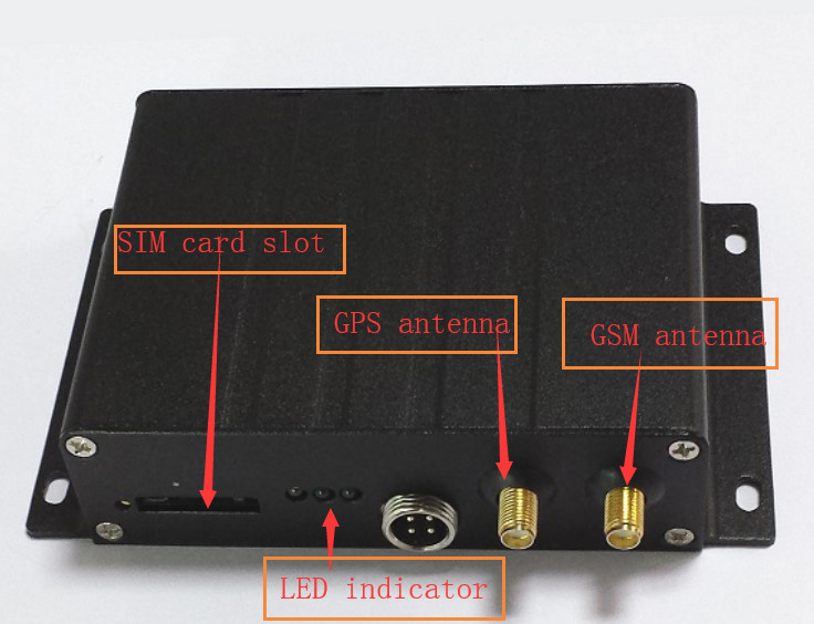
| GPS Sensitivity: | -159dBm | LED Indicator: | 4G(blue), GPS(green), Power(red) |
| Processing Chip: | STC | Speed Limiting Deviation: | ±5Km/H |
| Yellow Line: | No Need Connect | Green Line: | Connect The Control Line Of The Mechanical Actuator |
| Brown Line: | No Need Connect | White Line: | No Need Connect |
| Highlight: | vehicle gps tracking device,electronic engine governor |
||
Speed Limiter In Kenya For Car Truck Bus With Overspeed Alert And Speed Report
1. Product Brief:
The vehicle speed limiter CA100F is a vehicle terminal device can make accurate and intelligent vehicle speed Limiting. It can judge the vehicle speed by vehicle pulse speed data and GPS speed data precisely, and control the vehicle speed by intervening the throttle valve opening size.The user can set the speed limit value through the external digital display controller .
The product adopts intelligent STC chip, with high control precision, stable and reliable, will not affect the starting throttle, not affect the dynamic torque, only limit the maximum speed of the vehicle, control the throttle valve but will not lead to stalling, can ensure the throttle pedal can move freely in the allowable speed zone. It is a powerful and efficient intelligent vehicle safety products.
2. Product Function:
3. Technical Parameters:
| Name | No. | Color | Function | Signal Description |
| Electronic throttle limiter lines | 1 | Yellow line A+ | input(close to the accelerator pedal ) | Low throttle signal 0.36V |
| 2 |
Green line A- |
input(close to the accelerator pedal ) | high throttle signal 0.72V | |
| 3 | Brown line B+ | output(close to the ECU) | Low throttle signal 0.36V | |
| 4 | White line B- | output(close to the ECU) | high throttle signal 0.72V | |
| Mechanical throttle limiter lines | 1 | Yellow line | No need connect | |
| 2 | Green line | connect the control line of the mechanical actuator | High voltage signal output(the same with the power line) | |
| 3 | Brown line | No need connect | ||
| 4 | White line | No need connect |
4 The Mechanical Actuator
For the Electronic throttle ( EFI ) vehicles , no need add mechanical actuator, the limiter will simulate the voltage value of the vehicle throttle sensor, when the vehicle is over speed, The limiter will give ECU a idle voltage value, ECU will control the throttle according to this voltage value. When the vehicle is in normal driving state(not over speed), the speed limiter will not interfere the vehicle speed. The throttle sensor will give ECU normal driving voltage, let the vehicle keeping normal driving.
5 The Electronic throttle ( EFI ) Vehicle Speed Limiter Installation Steps
Specific Installation Steps:
(Take the truck speed limiter installation as an example)
① Take apart the protective shell which is beneath vehicle steering wheel, open the dashboard with tools, the speed limiter will be placed in this steering room.
② Find the vehicle accelerator pedal wires harness at first ,then find the two signal wires from the wires with multimeter test.
There are six wires in the accelerator pedal interface , two power wires ,two ground wires, and two signal wires. Start the vehicle, step on the accelerator pedal, let the vehicle in idle state, then the signal wire voltage value will change, thus you can find the signal wires.
After find the signal wires, please record the voltage value and make marks on the two wires , It will be convenient with the next step.
(Generally, the voltage value of the accelerator pedal signal wires is about 2 times of the other wire, and the low voltage is about 0.4V, and the high voltage is about 0.7V.)
③ Next, we set the voltage value of the brown wire and the white wire of the speed limiter to the value what we test from the vehicle accelerator pedal signal wire.
How to adjust the voltage value? At first, make the speed limiter power on, then take off the case cover of the speed limiter, slide the switch on the PCBA board to the "close" end, then we use the multimeter to measure the voltage value of the brown wire and the white wire. After adjusting the voltage, we need slide the switch back to the "broke" end.
![]()
We can find two adjusting knobs on the PCBA board. We take a screwdriver insert into the small knobs, screw it, then we can adjust the voltage of this two wires.
![]()
At first, we adjust the voltage value of the brown wire to the low value we measured form the accelerator pedal signal wire. ( The value of the actual measured voltage prevail. ) Then we adjust the voltage value of the white wire to the high value we get form the accelerator pedal signal wire. ( The value of the actual measured voltage prevail. )
Then , we can dot a little red glue onto the adjustable knobs to fix it, in order to prevent the adjustable knobs may appear small rotation in the long vehicle driving.
① Then , we connect the yellow, brown, green ,white wires to the original signal wire of the vehicle.
At first, we cut off the low voltage accelerator pedal signal wire. Connect the wire end which is close to the accelerator pedal to the yellow wire of the speed limiter . Connect the rest wire end to the brown wire of the speed limiter. Now it is turn to the other high voltage accelerator pedal signal wire, we also cut it off, Connect the wire end which is close to the accelerator pedal to the green wire of the speed limiter. Connect the rest wire end to the white wire of the speed limiter.
Features
Vehicle speed limiter
Speed limit, speed control device, suit all the cars, such as truck, heavy truck and tanker and so on.
Gps track record and overspeed car alarm
Electronic or Mechanical car throttle and tank truck suittable
Overspeed history data record
Description
1. Easy install, provide install video, suit all the cars(electronic and mechanical throttle);
2. Speed limit: set max speed, the speed won't over the setting speed, safe driving;
3. Connect with Google map and recording where you go;
4. 72hours Data Recording ( Overspeed History, Date & Time, Driver ID, GPS Location, tec.);
5. Bult-in Flash Menory for data recording with Encryption;
6. Overspeed Buzzer Alarm & Control before limiting speed;
7. No effect on vehicles's original brake, or ;normal operation;
8. Record various vehicle parameters
9. Check the history of the route;
6 Connection Diagram for Mechanical throttle
The Specific install Steps:
① Place the limiter host.
The limiter host can be installed in steering room ,a place will not not affect the driver operating. Please pay attention to fix it well, make the lines routing as hidden as possible.
② Install the limiter actuator and connect its drawing cable to vehicle throttle cable.
At first, we connect the actuator power line well, turn on the power, the actuator will spit its steel cable automatically , turn off the power until the cable completely spit out.
Then please step the accelerator pedal to the end state. Make the pull head of the actuator cable pass through the engine throttle control lever. Then cut off the excess portion, fixed the cable head well, make the drawing direction of the limiter steel cable and vehicle throttle cable negative, then fix the limiter well, there is a mounting bracket on the limiter body. Please install it in a appropriate position onto the vehicle with screws.
Mechanical actuator is used to control the throttle valve opening, when the vehicle speed in the normal range, the mechanical actuator will be in standby state, will not interfere the driver’s throttle operating. When the vehicle is in over speed state, the actuator will begin working, it will make the throttle valve mouth get smaller compulsively. The driver should not vigorously stamping step on the throttle. We shall not be responsible for the damage caused by this deed.
Note: You should choose the actuator model according to the working voltage of vehicle battery. So please tell us the vehicle voltage at first.
③ Connect the control wire of the limiter actuator to the limiter host, and connect the power line and ground line for the limiter actuator.
④ Connect the power line,ground line, ACC line, left-turning signal line, right-turning signal line, vehicle speed sensor signal line to the original vehicle lines one by one.
3) The Installation Test Method:
① Start the vehicle normally, stepped on the accelerator pedal, to check if the refueling is in normal state.If OK ,it means installation well,otherwise failure.
② In the refueling process, slide the switch (which is on the PCBA board) to the “close” end, then step on the accelerator pedal, if fueling is failure, it means the installation is successful, otherwise failure.
③ Wait about 3-4 seconds, then slide the switch (which is on the PCBA board) to the “broke” end, then step on the accelerator pedal, if you find refueling is in normal state, it means the installation is successful, otherwise failure.
Note: the above test process should not appear the phenomenon of stalling or automatic fueling. If appears, it means some problems exist.
if the test situation are the same with the above description, we preliminary estimate the connection and the adjusted idle voltage is right. To ensure the 100% right installation, we suggest that the driver take actual road driving test.
![]()
Content
Specs.
Dim.
105* 83 * 31 (mm)
Weight
240g
Network
GSM/GPRS/GPS
Band
850/900/1800/1900MHz or 4G
GPS chip
SiRF III chip
GSM/GPRS Module
SIM800 or SIM800C
Processing Chip
ARMSpeed limit Scope
40-120KM/H
Speed Limit Deviation
±5KM/HWork Voltage
DC 9V-36V
Mechanical Bearing Capacity
400NBattery
Chargeable changeable 3.7V / 650mAh Li-ion battery
Standby work current
< 200mA
Storage Temp.
-40°C to +85°C
Operation Temp.
-20°C to +70°C
Humidity
20%--90% non-condensing
7 Application Field:
Contact Person: Bryant
Tel: +86-13560742132
Fax: 86-0755-29437724