
|
|
|
Sales & Support
Request A Quote - Email
Select Language
|
|
|


|
Product Details:
Payment & Shipping Terms:
|
| Product Name: | Fuel Sensor GPS Tracker | Network: | 2G GSM |
|---|---|---|---|
| Band: | 850/900/1800/1900MHz | GPS Chip: | U-blox |
| GPS Accuracy: | Less Than 5m | Function1: | 700mm Capacitor Fuel Sensor |
| Work Voltage: | DC9-36V | Dim.: | 95*75*25mm |
| GPS Sensitivity: | -159dBm | Humidity: | 5%--95% Non-condensing |
| Operation Temp.: | -20°C To +70°C | Storage Temp.: | -40°C To +85°C |
| Color: | White | GSM: | SIMCOM900 |
| Function2: | Real Time Tracking | Function3: | Control Engine On Or Off |
| Highlight: | battery gps tracker,gps tracker with fuel sensor |
||
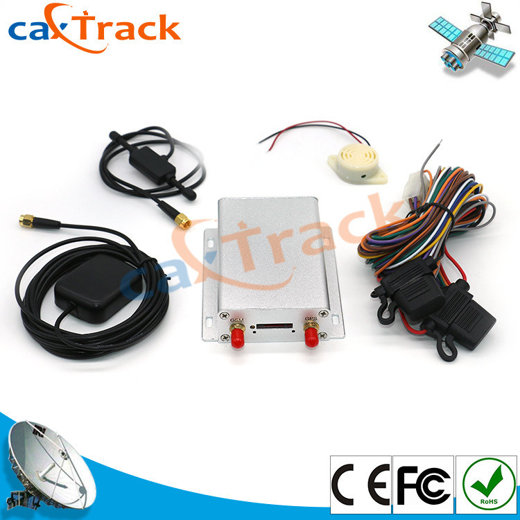
700mm Capacitor Fuel Sensor GPS Tracker Device Support 2G GSM Network
![]()
CA-V7 is one multi function GPS Device with UBLOX GPS Chip and 2G GSM module.
It supports fuel sensor ,camera,control engine on or off and so on.
Main Features:
1. Real Time tracking
2. History Track
3. Fuel sensor function
4. Temperature sensor function
5. one to four cameras
6. DC12V or DC24V relay
7. Micro phone
8. Mileage Statistics
9. SOS Alarm
Specification:
1. Device size: 87*64*26mm
2. Weight: 495g
3. Standby work consumption is less than 30mA
4. GPS Accuracy is less 5 meters
5. GPS Sensitivity: -159dbm
6. Work voltage: DC 9V to 36V
7. GPS Chip: Sirf 3 chip
8. GSM Module: SIM900 or SIM900A module
9. Network: GSM GPRS GPS
10. Band: 850MHz 900MHz 1800MHz 1900MHz
SMS Command:
1. Control Oil: Stopoil123456 is for stop oil , Supplyoil123456 is for supply oil.
123456 is the password of device.
2. Control Circuit: Stopelec123456 is for stop electricity. Supplyoil123456 is for supply electricity.
123456 is the password of device.
3. Change password: Password123456 654321, 123456 is old password, 654321 is old password.
Installation Diagram:
![]()
GPS Tracker should be installed by technical professional of local service center, without permission,
The user can not repair and move the tracker randomly. If users do, any unfortunity damage should
be compensated by himself.
Installation steps (caution: the following installation should under no power, otherwise will be dangerous.
1. Power supply line: The red wire connects 12V" +", black wire connects to GND.
2. Wire for cutting off oil of the tracker
Yellow wire connects the relay pin 86, 85pin to 12V DC, 87a pin and 30pin are in series power supply
circuits. Caution: Wrong connection of yellow wire will damage the tracker.
3. Wire for cutting off circuit of the tracker: White wire connects relay pin 86, 86pin to 12V DC, 87a pin
and 30 pin are in series power supply circuits. Caution: Wrong connection of yellow wire will damage
The tracker.
4. Emergency triggering alarm
The blue wire connects the positive of the alarm button, and the black wire connects the negative of
the alarm button.
Application:
1. School Bus
2. Truck
3. Taxi
4. car
5. Bus
History Track:
![]()
Real time Tracking
![]()
Contact Person: Bryant
Tel: +86-13560742132
Fax: 86-0755-29437724

